Brightfield Techniques
Background
Brightfield microscopy is one of the most basic light microscopy techniques whereby the sample is illuminated by white light that is transmitted through the sample onto the detector. There are different methods available to increase contrast in brightfield images (phase contrast, DIC, Polarized Light and Darkfield) which are available on different systems.
Types of Brightfield Imaging
Brightfield imaging or transmitted light microscopy usually has very low contrast between signal and background, therefore there are a number of techniques available which will be explained below.
Phase Contrast Microscopy
IMB Systems
- Fluoro3 (Olympus IX-80)
- Fluoro4 (Nikon TI-e)
- Nikon Deconvolution (Loanable objectives)
- Andor Dragonfly Spinning Disk (Loanable objectives)
Phase contrast microscopy is a technique used to increase contrast within transparent samples such as cells or thin tissue sections. The technique works by using an annulus at the condenser to only allow certain phases of light though the condenser and onto the sample. At the rear of the objective there is a matching (but inverted) phase plate, which blocks light let through the condenser annulus. Light that is diffracted by the sample will no longer be in the same phase and will bypass the phase ring and be directed onto the camera or imaging device.
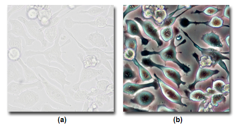
A comparision between A) Brightfield and B) Phase Contrast.
Source: MicroscopyU
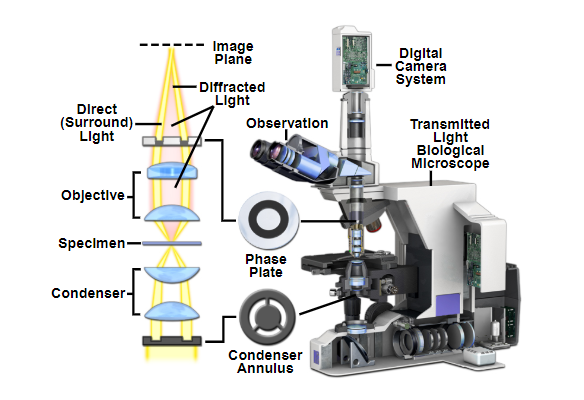
A cut-away of the light path of a phase contrast upright microscope. The condenser annulus is visible below the condenser which only allows through one phase of light. Above the sample plane the phase plate (or sometimes called phase ring) blocks one specific phase of light, and lets through any light that has been refracted by the sample.
Source: MicroscopyU
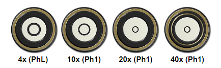
Examples of different Phase Rings on the back focal plane of different objectives.
Source: MicroscopyU
Microscopy: Darkfield and Phase Contrast Microscopy (Edward Salmon)
Link to MicroscopyU Phase Contrast Page
Differential Interference Contrast Microscopy
IMB Systems
- Fluoro1 (Olympus BX-51)
- Fluoro2 (Zeiss Apotome)
- Nikon Deconvolution
Differential Interference Contrast (DIC) microscopy is a method used to enhance the contrast of transmitted light images by using polarization of light. By the introduction of two Nomarski prisms (one above and one below your sample), light is sheered into two discrete polarizations which interfere with one-another at the sample plane.
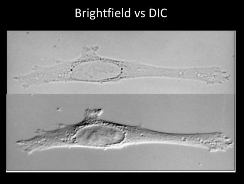
A comparison of Brightfiled vs DIC microscopy techniques.
Source Richard McIntosh
As light passes through the sample where small changes in refractive index occur (eg the presence of cellular membranes) the two polarizations will be affected, and hence the interference will change, altering the resultant image.
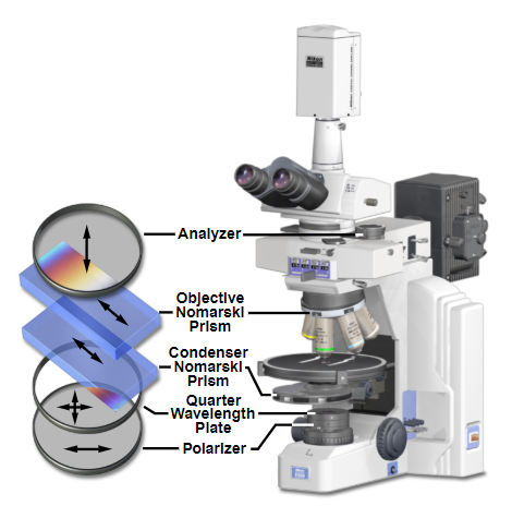
DIC LightPath in an upright microscope. Here the two Nomarski prisms are visible above and below the sample stage. Note in this arrangement there is also a fixed polarizer and attached Quarter wavelength plate which allows you to rotate 90 degrees in the imaging plane.
Source: MicroscopyU
Microscopy: Differential Interference Contrast (DIC) Microscopy (Edward Salmon)
Polarized Light Microscopy
IMB System
- Stereo 2 (Nikon SMZ-18)
Polarized light microscopy is a contrast enhancing technique that improves resultant images where the sample being imaged has birefringent properties. This technique is often used for materials science, however can be very useful for some biological applications.
Normal white light is unpolarized, however optical elements can filter only one specific polarization as per the image below.
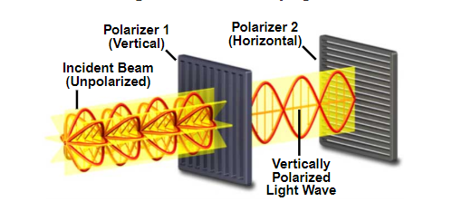
Principles of light polarization diagram.
Source: MicroscopyU
In a polarized light microscope a polarizing filter is added immediately after the brightfield light source and an additional polarizing filter is fitted above the sample before the eyepieces or image capture device. The polarizer below the sample is usually adjustable by rotation to select for different polarization angles. See the light path diagram below.
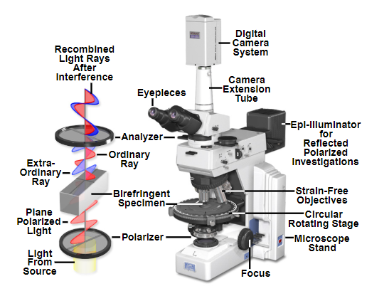
Light path of a polarized light microscope. Note the polarizing filter below the sample and the analyser above the sample which allow discrete polarizations through.
Source: MicroscopyU
Polarization light microscopy allows for greater contrast to be observed in samples such as fibers (see below).
Example of nylon fibers viewed under widefield and polarized light.
Source: MicroscopyU
Microscopy: Polarization (Edward Salmon)
Link to MicroscopyU Polarization Microscopy Page
Darkfield Microscopy
IMB System
- Brightfield/Darkfield (Olympus BX-51)
Darkfield microscopy is a technique to increase contrast in your image when the refractive index of your sample very closely matches the refractive index of your imaging media. The technique works by blocking the light that comes directly onto the sample, and instead relies solely on stray rays of light to illuminate the sample from the image border.
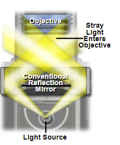
Example of a darkfield light path below the sample plane, where only stray rays of light are collected into the rear of the objective.
Source: MicroscopyU
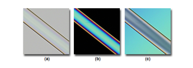
In the images below, the fibers do not appear to have a lot of contrast (a), however when illuminated by darkfield microscopy (b) much more contrast is apparent. In some circumstances you have too much contrast (c) when using conventional brightfield, this can also be improved when using darkfield (d) where less contrast is achieved.
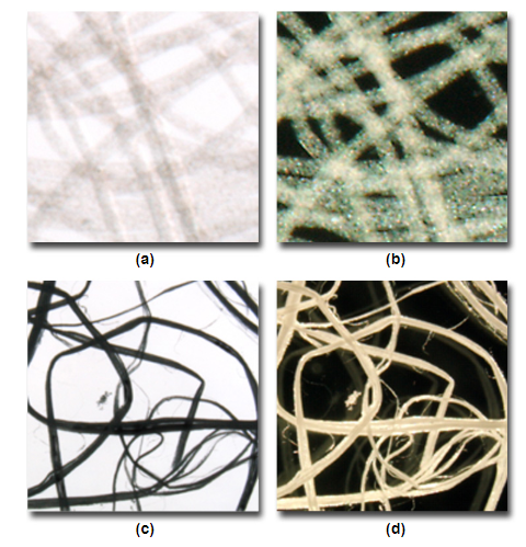
Comparisons of high and low contrast samples with brightfield (a,c) and darkfield (b, d).
Source: MicroscopyU
Microscopy: Darkfield and Phase Contrast Microscopy (Edward Salmon)
Link to MicroscopyU Darkfield Microscopy Page
Kohler Illumination
Ensuring the condenser is in the right position is vital for all of these techniques. To perform the correct alignment on the condenser requires a technique called Kohler Illumination, which examples and further explanations can be found here.